|
|
|
|
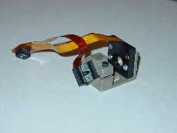
Laser Attenuator (LA)
|
|
|
Liquid Crystals have a
variety of other Electro-Optic uses. Shown to the left is a laser
attenuator with optical feedback designed for high end commercial laser
jet printing engines. This application required fast response time,
wide operating temperature range, high incident power handling, and low
reflectivity.
|
|
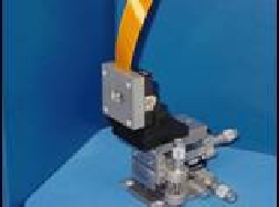
Variable Optical Attenuator (VOA)
|
|
|
Shown to the left is a
device used for variable optical attenuation for telecommunications
applications. It is a 32 channel device which has 35dB attenuation
range, the insertion loss is <-.29dB. It is designed to operate in
the C and L bands.
|
|
Optical Cross Connects (OXCs)
|
|

|
Optical Cross connects or
switches of high dynamic range can easily be constructed with liquid
crystal technology. Shown to the left is a single channel optical cross
connect. This device has a fast response time (<20mS), large dynamic range (>40dB),
and wide operating range (-10 to +85). This device can be configured to
operate at any wavelength.
|
|
Optical Add Drop Module (OADM)
|
|

|
Optical Add Drop Modules
(OADMs),or Reconfigurable Optical Add Drop
Modules (ROADMs),are required when information or wavelengths are
required to be added too or removed from a data stream on the internet.
These configurations can be easily accomplished with liquid crystal
technology with the added advantage of channel equalization due to the
analog nature of liquid crystals. Shown to the left is a 100 channel
device used in a OADM application.
|
|
Polarization Control (PC)
|
|

|
Liquid crystals are inherently,
variable waveplates. A typical retardence curve for our devices is shown to the
left. For telecommunications applications, Polarization Mode Dispersion
(PMD) is a prominent problem in Ultra Long Haul and Long Haul Fiberoptic applications where existing standard
fiber is in place. A single channel or multi channel
device can be easily constructed to mate with a single fiber or bundle
of fibers or wavelengths to reorient the polarization state such that
it is preserved and signal degradation is minimized.
|
|
Dynamic Gain Equalizer (DGE)
|
|
|
Shown to the left is an
array of DGEs in process just prior to the algnment
coating step coating. These units are 32 channel, reflective gold
devices. The inter-channel spacing is 2.5um, with a channel width of
100um. This device is designed for C band (1528 - 1561nm) operation.
|
|
|
|
|
|Home| |Principals| |Services|
|Design Capability| |LC For
Telecom| |Our Technology| |Industry Links| |FAQ|
|Contact Us|
|